Customizing the viewer settings
The tables on the Viewer tab let you modify the visual aspects and the display settings of the 2D viewer.
You can modify the setting in the following tables:
- Colors lets you define colors for various PCB entities and other elements in the viewer.
- Controls lets you enable or disable the display of filled polygons for multiple entities and specify the line intersection threshold ratio.
- Measurement lets you define colors of the measurement mode options.
- Bends lets you define the colors of the bends, and the bends information dialog box.
Customizing the display colors in the viewer allows you to align the visual representation of your PCB design with your organization's standards, facilitating a smooth collaboration and effective communication among team members.
- Use the slider to change the color spectrum and select a color from the colors window.
- Define a specific color.
- Use the color dropper tool to select a color from your screen.
Colors
The following table lists the settings that you can modify in the Colors table.
| Option | Description |
|---|---|
| Background | Sets the background color of the viewer and, on the PCB tab, the board thickness viewer. |
| Text | Defines the text color of the measurement mode options.
|
| Selection | Specifies the color of selected entities from the entities interactive tables and the viewer.
|
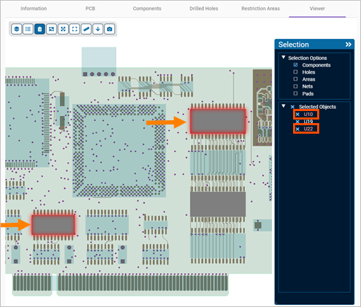
| Highlight | Sets the color used to highlight the elements that you select in the Selection toolbox.
|
| Board and Holes | Specifies the color for the board and holes in the PCB assembly. |
| Stackup Zones | Specifies the color for the stackup zones in the PCB assembly. |
| Top Components | Defines the color for the components that are mounted on the top layer of the PC board. |
| Bottom Components | Defines the color for the components that are mounted on the bottom layer of the PC board. |
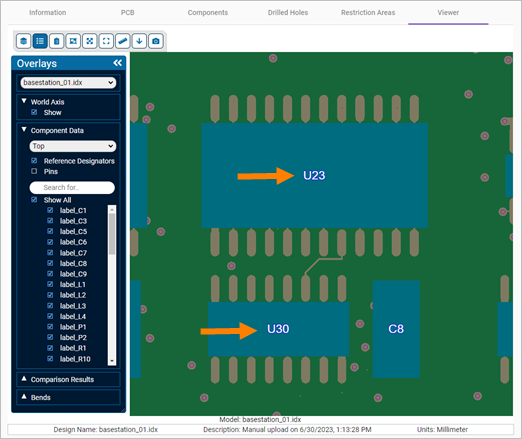
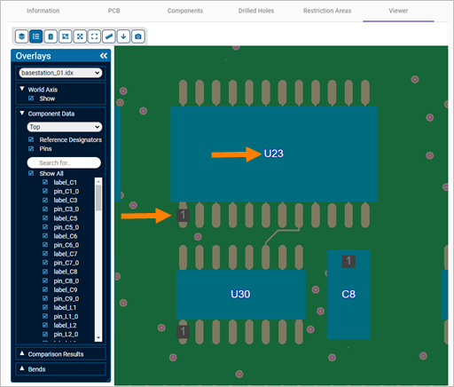
| Components Label | Sets the color for the PCB components labels when you display them from the Overlays toolbox.
|
| Top Components Label Outline | Sets the color of the labels outline for the PCB components mounted on the top layer of the PC board when you display them from the Overlays toolbox. |
| Other Components Label Outline | Sets the color of the labels outline for the PCB components that are not mounted on the top layer of the PC board when you display them from the Overlays toolbox. |
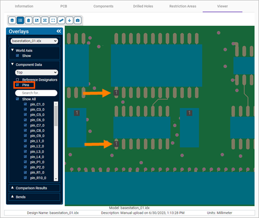
| Component Pins | Specifies the color of the PCB components primary pins label.
|
| Predefined and Random Colors for Layers | Enables or disables the customization of layers display using predefined random colors.
|
| Predefined and Random Colors for Drill Layers | Enables or disables the customization of drill layers display using predefined random colors.
|
| Other Layers (Without Copper) | Defines the color for other layers in the PCB assembly, excluding copper. |
Controls
The following table lists the settings that you can modify in the Controls table.
| Option | Description |
|---|---|
| Labels Font Size (px) | Sets the font size, in pixels, for the components and primary pins labels when you display them from the Overlays toolbox.
|
| Display of Board as Filled Polygons | Controls the display of the board, routes, and breakouts. When you select Enable the board is displayed as a filled polygon. When you select Disable the board is displayed as an outline. |
| Display of Components as Filled Polygons | Controls the display of the components. When you select Enable the components are displayed filled polygons. When you select Disable the components are displayed as outlines. |
| Display of Pads as Filled Polygons | Controls the display of the pads. When you select Enable the pads are displayed as filled polygons. When you select Disable the pads are displayed as outlines. |
| Display of Copper as Filled Polygons | Controls the display of the copper. When you select Enable the copper is displayed as a filled polygon. When you select Disable the cooper is displayed as an outline. |
| Display of Areas as Filled Polygons | Controls the display of the areas. When you select Enable the areas are displayed filled polygons. When you select Disable the areas are displayed as outlines. |
| Line Intersection Threshold Ratio | Controls object selection proximity, in percentage, when rendering with line meshes instead of polygons, allowing you to precisely adjust the required closeness when selecting objects. |
Measurement
The following table lists the settings that you can modify in the Measurement table.
| Option | Description |
|---|---|
| Points Color | Specifies the color of measurement points displayed in the viewer. |
| Dialog Background Color | Sets the background color of the measurement dialog box. |
| Dialog Foreground Color | Defines the color of the text and elements in the measurement dialog box. |
| Dialog Close Button Color | Sets the color of the close button in the measurement dialog box. |
| Dialog Opacity (in %) | Adjusts the opacity level, in percentage, of the measurement dialog box. |
Bends
The following table lists the settings that you can modify in the Bends table.
| Option | Description |
|---|---|
| Line Color | Specifies the color of the bends in the viewer. |
| Display Label | Enables or disables the display of bend labels in the viewer. |
| Dialog Background Color | Sets the background color of the bends dialog box. |
| Dialog Foreground Color | Defines the color of the text and elements in the bends dialog box. |
| Dialog Close Button Color | Sets the color of the close button in the bends dialog box. |
| Dialog Opacity (in %) | Adjusts the opacity level, in percentage, of the bends dialog box. |
| Dialog Level of Detail |
Available when Display Label is enabled. Specifies the level of detail of bend labels. Full displays the following detailed bend information:
Minimal displays only the bend IDs. |

