Review the collaboration history
This example shows how to review the history of changes and collaboration metrics in the interactive table and the 2D viewer of the collaboration functionality.
Before following these steps, you need to log in to the web application.
-
Click Collaboration
 to open the collaboration
functionality.
If you are not logged in, nothing happens when you click the command.
 -
Click
 to provide the absolute path to a new collaboration session directory, which must be accessible by the server where the web app is installed.
When you use the IDX format to exchange electromechanical data between ECAD designers and MCAD designers via ECAD-MCAD collaboration, the information is exchanged through IDX files located in the collaboration session directory.
 -
Click Results to review all the IDX files stored in the
collaboration directory.
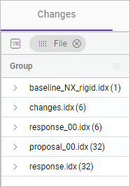
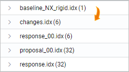
The application presents all the IDX files, which are stored in the selected collaboration session directory, in a table on the Changes tab. The corresponding number of changes made to each file are shown in the parenthesis.

-
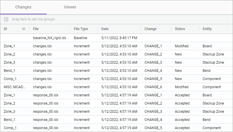
Remove File from the grouping row and explore the table
structure, including column headers and rows, to understand the data it
contains.
In the following example, the table displays details for the following files: baseline, proposed changes, and responses. This includes information such as the date and time of the last saved modification, file type, modification status, and the PCB entity type that was changed.

-
You can explore these changes by filtering the data or by grouping the data.
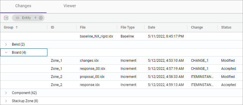
For example, drag-and-drop the Entity header to the group
row to explore the number of changes made for each PCB entity. In this example,
the design of the board was modified four time.

-
On the Viewer tab, animate the step-by step changes in
the collaboration directory by clicking play
 in the graphics
window.
Every time you click the play button, the viewer sequentially displays design changes within each IDX file.
 In this example, the history of design changes is displayed through animation. First, the component is relocated, resulting in a transformation of the board from rigid to rigid-flex, with the addition of the bend. Next, a group of components was added to the upper left section of the board.
 -
On the viewer command ribbon, click Overlays Toolbox
 to open the
Overlays toolbox.
In the Comparison Results group, in the Components Changes sub-group, you can display or hide components of the design that have been changed.
