Viewer interface
The commands on the Viewer tab let you visualize the PCB entities and their attributes when using the assembly, comparison, and collaboration functionalities.
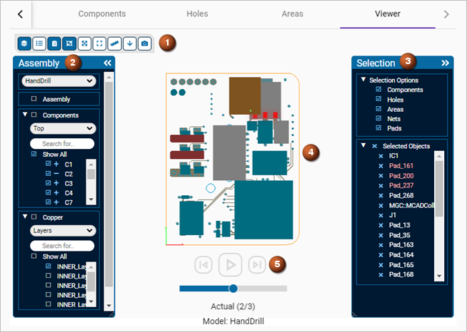
Viewer tab
| Option | Description |
|---|---|
| (1) Viewer command ribbon | Lets you open and close toolboxes to display specific PCB entities and attributes, and measure the distance between them. You can also modify the model position to better inspect the design. |
| Opens or closes Assembly toolbox (2) that lets you specify which assembly, components, copper layers, and other layers to display. | |
| Opens or closes the Overlays toolbox that lets you specify which additional component data such as labels or pins to display. The specified entities are superimposed on the displayed model. | |
|
Opens or closes the Selection toolbox (4) that displays the entities that you selected in the viewer toolboxes, the interactive tables or directly in the graphics window. When you click a selected entity, the software highlights it on the 2D layout of the PCB design. |
|
| Enables or disables the selection feature that lets you select PCB entities directly on the model to graphically inspect them. Use this command in conjunction with the Selection toolbox for better precision, for example, when selecting entities. | |
| Resets the model to the original position. | |
| Zooms into the area surrounding the selected PCB entities, and automatically adjusts the opacity of the model to highlight the selection. | |
| Lets you measure the spacing between PCB entities and attributes in millimeters. Select the Snap to Geometry Points check box and specify two points on the edge of a PCB entity or attribute to display the shortest X and Y distance values between the points. | |
| Displays the bottom board side. | |
| Displays the top board side. | |
| Captures an image of the displayed model and lets you save it as a PNG file. | |
| (3) Graphics window | Displays a 2D layout of the PCB design. You can customize the viewer options on the Settings main page. |
| (5) Animation commands | Available when using the comparison and collaboration functionalities. Lets you inspect the design history in an animated format.
|
Assembly toolbox
The Assembly toolbox lets you specify and select the PCB
entities that display in the graphics window to better inspect the design. You
display entities by selecting the check box next to them. To add PCB entities to the
Selected Objects, click the ![]() icon. You
can also search for specific entities using the search boxes.
icon. You
can also search for specific entities using the search boxes.
| Option | Description |
|---|---|
| Assembly | Displays or hides the PC board, the stackup zones, or the bends to let you more easily inspect the components, copper entities, restriction areas and drilled holes. |
| Components | Displays or hides all PCB components. You can also control all components that are on the top or bottom board side. |
| Copper | Displays or hides all copper entities. You can also control all copper restriction areas on layers or all copper nets. |
| Other Layers | Displays or hides all restriction areas except copper areas and drilled holes. Copper areas are under Copper when you select the Layers list. You can also control restriction areas and drilled holes separately. |
Overlays toolbox
| Option | Description |
|---|---|
| World Axis | Displays the absolute coordinate system of the PC board. |
| Component Data | Lists component reference designators and primary pins per component filtering list. |
| Comparison Results | Available when using the comparison functionality. Lists PCB entity design changes by board side. Board Change displays the changes made to the board with an orange outline. Components Changes, Holes Changes, Areas Changes, and Nets Changes list the design changes for components, holes, restriction areas, and nets. |
| Bend Labels | Lists the bends that exist in the flexible or rigid-flex PCB design. |
Selection toolbox
| Option | Description |
|---|---|
| Selection Options | Lists the available options that you can select to further explore the PCB design.
For example, to select a drilled hole near a bigger component, make sure that the Holes check box is selected and clear the Components check box to easily select the drilled hole instead of the component next to it. |
| Selected Objects | Lists all PCB entities selected using the toolboxes and cross-selected in interactive tables. Click x next to the entity to remove it from the selection list. When you select an entity from this list, it is highlighted in the graphics window. |